Into the Transceiver-Verse Part II: A Galaxy of Transceiver Types

In the first blog of our Into the Transceiver-verse series we focused on the 6 questions you need to ask when selecting transceivers for your network application. Knowing what questions to ask is half the battle in choosing; the other half is knowing what’s available. Transceiver types can be grouped in any number of ways (by form factor, data rate, coding, platform etc…). For the sake of simplicity, here we’ll group them as follows:
- Copper & Aggregated Solutions
- Gray (Wideband)
- WDM (Wavelength Division Multiplexing)
- BiDi (Bidirectional)
- PON (Passive Optical Network)
- Coherent
Copper & Aggregated Solutions
| Form Factor | Type | Data Rate | Max Distance | Medium | Connector | λ |
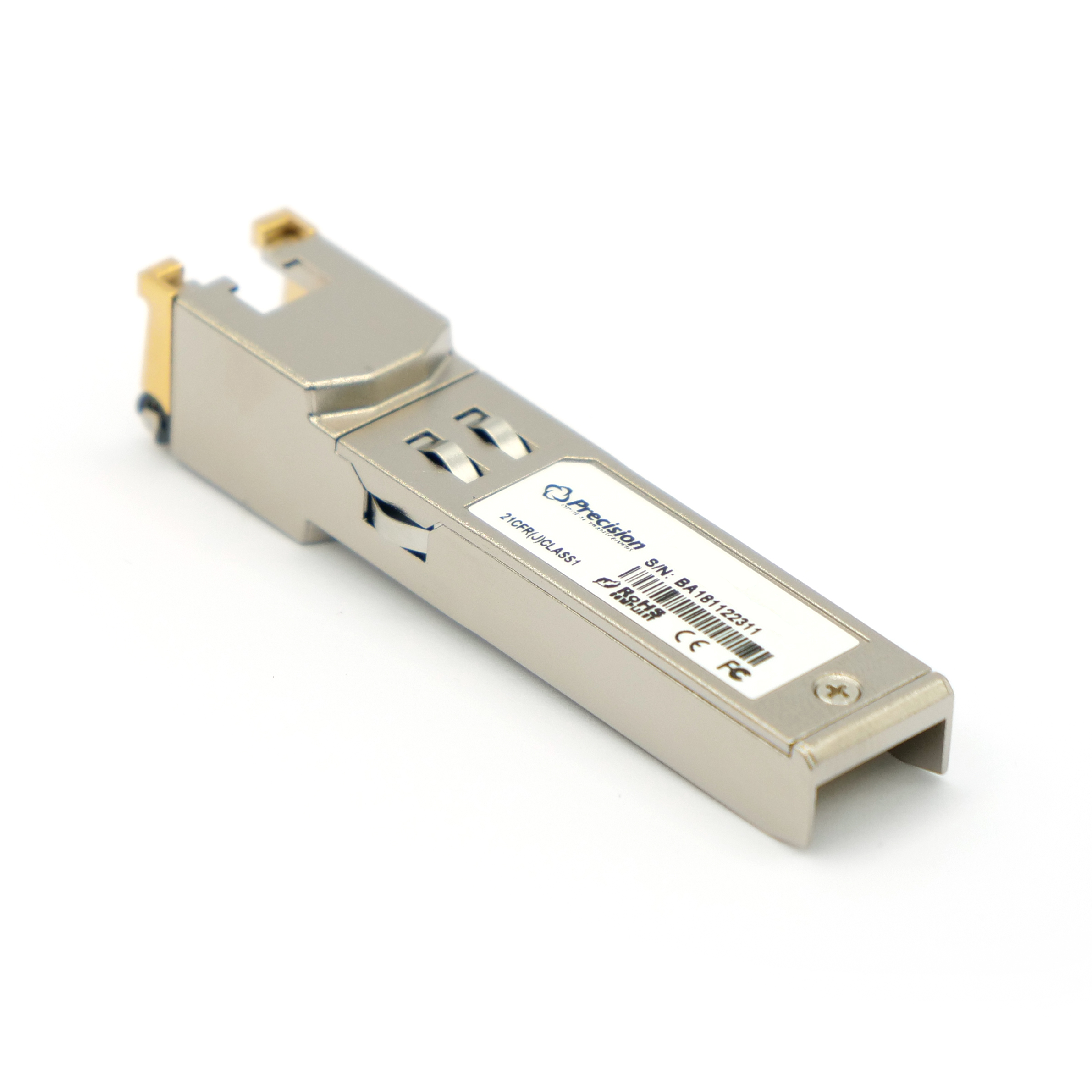
| SFP | Copper | 1G | 100m | Cat5 | RJ45 | NA |
| SFP+ | Copper | 10G | 50m | Cat6A/7 | RJ45 | N/A |
Table 1 – Copper Transceivers in the 1G SFP and 10G SFP+ form factor.
Also note, the Copper 1G can come in single rate, 1G or in a tri-rate 10Mb/100Mb/1000Mbps design.
Two types of transceivers that don’t quite fit into the other categories are the DAC (Direct Attach Cable) and AOC (Active Optical Cable). A DAC is a copper cable hardwired into a transceiver on each end of a link while an AOC is similar but with an optical fiber “hardwired”/embedded into transceivers on each end. They come in multiple lengths and break-out configurations, including the popular 4x 10G SFP+ aggregating into 1x QSFP.
Aggregated solutions have some pros and cons. On the plus side, AOCs and especially DACs are extremely low cost and low power. The aggregated solution provides a lower SKU count upfront as optical jumper components & transceivers are kitted together. On the downside, if a single component of the assembly fails you have to replace the whole cable+transceiver assembly, whereas with disaggregated solutions you just replace the item that fails. Also for sparing, AOCs and DACs are discrete lengths so you would have to keep 1 spare AOC or DAC assembly for every length cable needed in your network instead of just keeping a spool of cable and a few different types of transceivers. Consider long term network planning and maintenance when deciding whether to go with an aggregated or disaggregated (transceivers and cables sold and installed separately) solution. For example, in some of the latest technology developments like 400G transceivers, 400G DAC cables offer by far the lowest cost per 100G, however, because of its thick shielding to protect from interference, the bend radius is pretty restrictive, which makes dealing with proper in-rack installation and operations troubleshooting very problematic for field technicians.
Gray Optics
Wideband (or non-channelized) optics are often referred to as “Gray”. The types of laser emitters used in Gray transceivers have a wide spectrum. That is to say, the center wavelength may be 850nm, for example, while the actual measured wavelength could range anywhere from 830-870nm. So a +/-20nm tolerance is assumed for a source with center wavelength 850nm.
| Form Factor | Type | Max Distance | Medium | Connector | λ |
| SFP | Gray SX | 500m | MMF | LC Duplex | 850nm |
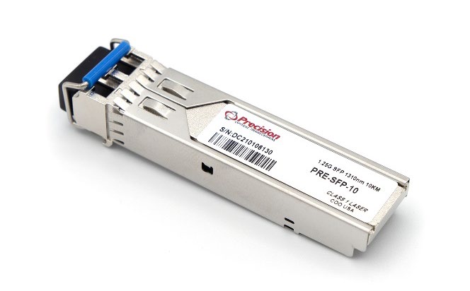
| SFP | Gray LX | 10km | SMF | LC Duplex | 1310nm |
| SFP | Gray EX | 40km | SMF | LC Duplex | 1310nm |
| SFP | Gray ZX | 80km | SMF | LC Duplex | 1550nm |
| SFP | Gray EZX | 120km, 160km | SMF | LC Duplex | 1550nm |
| SFP+ / XFP | Gray SR | 300m | MMF | LC/ UPC Duplex | 850nm |
| SFP+ / XFP | Gray LR | 10km | SMF | LC/ UPC Duplex | 1310nm |
| SFP+ / XFP | Gray ER | 40km | SMF | LC/ UPC Duplex | 1550nm |
| SFP+ / XFP | Gray ZR | 80km | SMF | LC/ UPC Duplex | 1550nm |
| SFP+ / XFP | Gray EZR | 100km | SMF | LC/ UPC Duplex | 1550nm |
Table 2 – Gray Transceiver Types in the 1G SFP and 10G SFP+/XFP form factor.
What does the SX, LX, EX, ZX and EZX mean?
S, L, E, Z indicate the wavelength of the laser and reach(distance) of the transceiver.
S = Short wavelength (850nm)
L = Long Wavelength (1310nm typically up to 10km)
E = Extended Reach wavelength (1310/1550nm up to 40km)
Z = Extra – Long Wavelength (1550nm up to 80km)
EZ= Extra ZX/ZR wavelength (1550nm up to 120km)
X = stands for External Sourced coding, which translates into 8 bit and 10 bit encoding type (required for 1 G).
Similarly, next to the SFP+ types you’ll see the S, L, E & Z again, but followed by an R instead of an X. The R indicates ScRambled coding, specifically “64 bit 66 bit encoding type” which is required for 10G (also 40G and 100G ethernet protocols). Sometimes written as 64B66B or 64b/66b, it is a line code that transforms 64-bit data to 66-bit data.
WDM (Wavelength Division Multiplexing)
WDM (Wavelength Division Multiplexing) transceiver types are divided into CWDM (Coarse WDM) and DWDM (Dense WDM). These are transceivers specifically designed to be used in WDM systems.
| Form Factor | Type | Max Distance | Medium | Connector | λ |
| SFP | CWDM EX | 40km | SMF | LC Duplex | CWDM |
| SFP | CWDM ZX | 80km | SMF | LC Duplex | CWDM |
| SFP | CWDM EZX | 120km, 160km | SMF | LC Duplex | CWDM |
| SFP | DWDM EX | 40km | SMF | LC Duplex | C-Band |
| SFP | DWDM ZX | 80km | SMF | LC Duplex | C-Band |
| SFP | DWDM EZX | 120km, 160km | SMF | LC Duplex | C-Band |
| SFP+ / XFP | CWDM ER | 40km | SMF | LC/ UPC Duplex | CWDM |
| SFP+ / XFP | CWDM ZR | 80km | SMF | LC/ UPC Duplex | CWDM |
| SFP+ / XFP | DWDM ER | 40km | SMF | LC/ UPC Duplex | C-Band |
| SFP+ / XFP | DWDM ZR | 80km | SMF | LC/ UPC Duplex | C-Band |
Table 3 – CWDM and DWDM Transceiver Types in the 1G SFP and 10G SFP+/XFP form factor.
CWDM – the wavelengths are typically anywhere from 1430 to 1610 with 20nm spacing (because you can have a 1430 transmitting optic that might have a tolerance of +-6.5nm so the spacing helps prevent the next channel overlapping with the channel you’re using).
DWDM – Most DWDM wavelengths fall into the C-band (see the Standard Wavelength Reference Table). Note the relationship between the ITU channels and frequency: if you ignore the initial “19” and move the decimal point over 2 spaces to the left, you get the ITU channel (Ex. 196000GHz = ITU channel 60.00, 195950 GHz = ITU channel 59.50).
DWDM Transceivers are available in either a Fixed Channel or Tunable version. Both are available in C-Temp or I-Temp versions.
- Fixed-Channel DWDM optics – Each optic is a fixed wavelength / ITU channel and can be deployed only as such
- Tunable DWDM optics – Each optic is tunable within the full ITU spectrum of wavelengths. Optic can be tuned as needed to meet the required wavelength
An easy way to think about the difference between fixed-channel optics vs tunable optics is that the fixed-channel optics are like a box of crayons where you have a different transceiver for every color vs a tunable optic which is like a pen that comes with all the different colors you can just click into place. This is what makes the tunable option preferable as far as sparing. Instead of keeping a spare fixed channel transceiver for every wavelength, you just need one tunable.
As you might have noticed in both Table 2 and Table 3, the Max Distance that the optics can achieve is limited to 80-100km for 1G to 10G transceivers. The main culprit for this limitation is dispersion. Dispersion is a physical limitation of optical fibers that can be briefly described as the broadening of the optical pulses as they travel across the fiber. The longer the distance it travels, the worse the effect is. This makes it harder for the receiver to differentiate adjacent pulses/bits of information and eventually produces an increase in Bit Error Rate. You can learn more about Chromatic Dispersion and the limitations it adds to DWDM systems by downloading this free eBook.
A summary and comparison of Gray, CWDM and DWDM optics is shown below, including the data rates available for each.
| Technology | Wideband (Gray) | CWDM | DWDM |
| Wavelengths (nm) | 850, 1310, 1550 | 1430 – 1610 | ~1520 – 1570 |
| Max Capacity (Single Fiber) | 1-3 Channels | 16 Channels | 160 Channels |
| Relative Cost | Low | Medium | High |
| Tunable Availability | N/A | No | Yes |
| Data Rates Available (Gbps) | 1, 10, 25, 40, 100, 200, 400 | 1, 10, 100* | 1, 10, 25**, 100, 400 |
Table 4 – Summary of Gray, CWDM and DWDM Transceiver Types
* 100G CWDM uses 1271, 1291, 1311, 1331 wavelengths
** 25G DWDM SFPs are new but not widely used because of link budget limitations
Bidirectional Transceivers
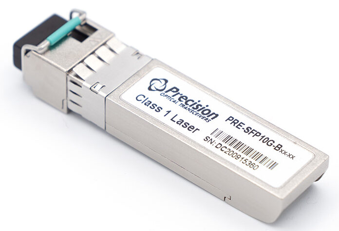
Most transceivers have a TOSA (Transmitter Optical Sub Assembly) and a ROSA (Receiver Optical Sub Assembly) but if the two are combined into a single unit, it becomes a BOSA (BiDirectional Optical Sub Assembly). For short, we call this combined unit a BiDi. BiDis are beneficial in that they allow for a single fiber solution and have the following characteristics:
- A pair is required
- 4 different pair types available
- 1270/1330nm (10G)
- 1310/1490nm (1G)
- 1310/1550nm (1G)
- 1490/1550nm (1G or 10G)
- Can use either a 1270/1330nm or a 1310/1490nm pair in the express port of a DWDM mux
| Form Factor/Type | Type | Max Distance Available (km) | Line Rate | Medium | λ |
|---|---|---|---|---|---|
| SFP | BIDI | 10, 40, 80, 120, 160 | 1G | SMF | CWDM |
| SFP+ | BIDI | 10, 20, 40, 60, 80 | 10G | SMF | CWDM |
| XFP | BIDI | 10, 20, 40 | 10G | SMF | CWDM |
Table 5a BiDi for CWDM, BiDi, LC connector, 1G-10G
| Form Factor | Type | Max Distance | Line Rate | Medium | Connector | Electrical Interface | Optical Interface | λ |
|---|---|---|---|---|---|---|---|---|
| SFP28 | BIDI | 10, 20km | 25G | SMF | Simplex LC | C27/C33 | ||
| SFP28 | BIDI | 30, 40km | 25G | SMF | Simplex LC | C27/C31 | ||
| QSFP | SR BIDI | 150m | 40G | MMF | Duplex LC | 4x10G NRZ | 2x20G PAM4 | 850/900nm |
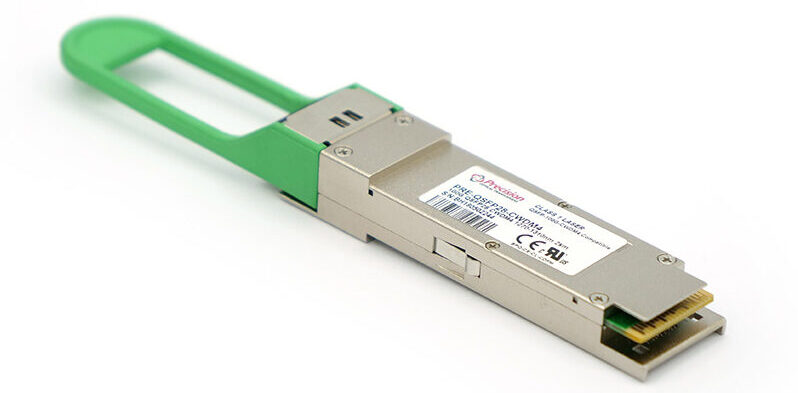
| QSFP28 | CWDM4 BIDI | 2km | 100G | SMF | Simplex A-LC | 4x25G NRZ | 4x25G NRZ | C27-C33 |
Table 5b BiDi’s 25 – 100G
Moving up from 10G hardware into 25G hardware, BiDi’s are a bit more common. Similar to 1G and 10G BiDi’s you’ll have 1 optical port, but instead of 1x transmit and 1x receive, you’ll actually have 2x transmit and 2x receive signals. This is a way to combat some of the chromatic dispersion concerns if you were using one optical signal at 25G. The C27, C31 and C33 should not be confused with DWDM Channels 27 and 31. The C in this case is for CWDM wavelengths 1270, 1310, and 1330. DWDM wavelengths are typically referred to by their ITU channel. Currently, 25G SFPs are capped at 40km but the industry is making efforts to improve that distance. It is currently offered in wideband 1310 but the hope is to eventually have the DWDM reach 40km.
PON
Passive Optical Networking(PON) uses unpowered components such as beamsplitters to distribute a single data signal into multiple branches. Below are the form factors currently available for PON hardware, including the introduction of a new type of SFP form factor which is called SFP-DD(Dual Density). Dual Density is essentially 2 SFPs in 1.
| Form Factor | Type | Max Distance* | Line Rate | Medium | Connector | l (nm) |
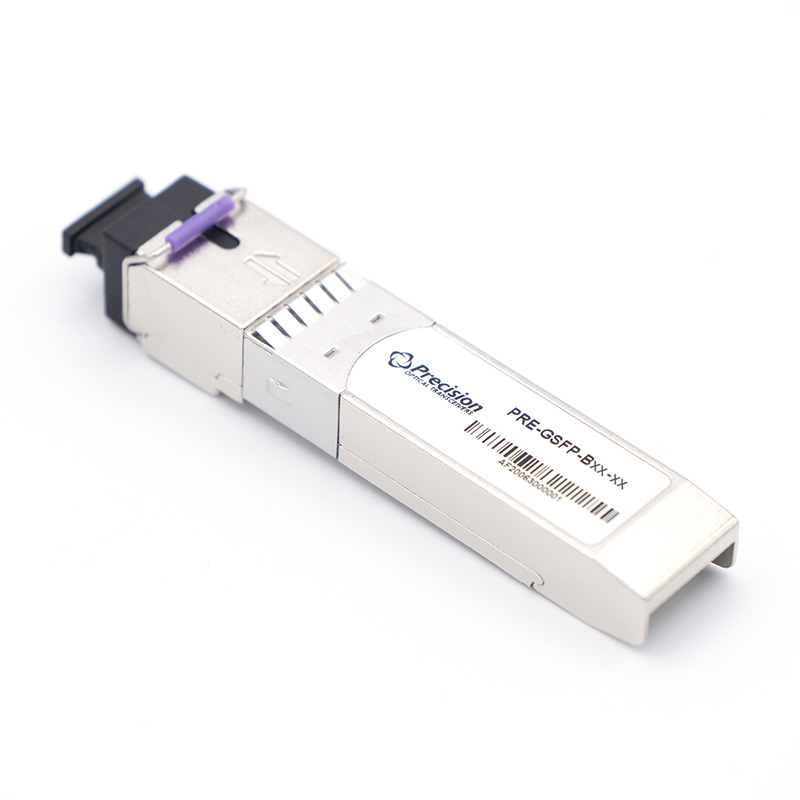
| SFP | GPON | B+, C+ | 2.5G | SMF | SC Simplex | 1490/1310 |
| SFP+ | XGS/PON | N1, N2 | 10G | SMF | SC Simplex | 1577/1270 |
| SFP+ | XGS/GPON Combo | N1, B+ | 2.5/10G | SMF | SC Simplex | XGS/GPON |
| SFP+ | XGS/GPON Combo | N2, C+ | 2.5/10G | SMF | SC Simplex | XGS/GPON |
| SFP-DD | XGS/GPON Combo | N1, B+ | 2.5/10G | SMF | SC Simplex | XGS/GPON |
| SFP-DD | XGS/GPON Combo | N2, C+ | 2.5/10G | SMF | SC Simplex | XGS/GPON |
| XFP | XGS PON | N1, N2 | 10G | SMF | SC Simplex | 1577/1270 |
| XFP | EPON | PR30 | 1G/10G | SMF | SC Simplex | 1577/1270 |
Table 6 PON Transceiver Types
*Max distance for PON is best interpreted by link budget rather than a distance rating
| Type | Link Budget |
| B+ | 29.5dB |
| C+ | 35dB |
| N1 | 29dB |
| N2 | 31dB |
| PR30 | 31.8dB for 1G / 30dB for 10G |
Most PON hardware is also BiDi. For the GPON types, there is 1490 / 1310. XGS/PON transmits typically at 1577nm and receives at 1270.
As shown in Table 6 above there are XGS/GPON combo SFPs available allowing GPON operators to gradually transition into XGS/PON – this enables one to buy a single hardware to be purposed for two generations of technology. There is some caution using this technology because it can make you single sourced since the PCB connector on the combo is different from the standard GPON or XGS/PON optic separately.
Coherent
Coherent optics have been a game-changer for networking. Fiber networks have been forever altered by the benefits coherent optical transceivers have delivered: much greater capacity and flexibility, higher bit-rates and better overall performance, to name a few. Coherent systems have kept costs down by saving companies from needing to lay more fiber.
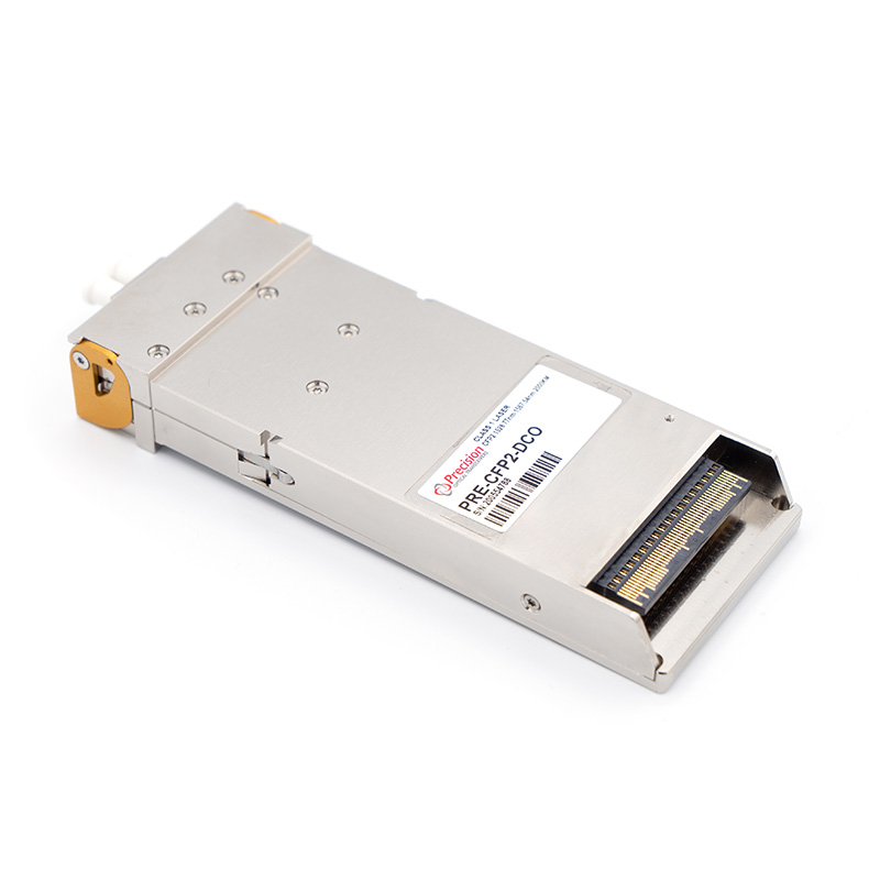
A series of 100G DWDM pluggable transceivers including CFP DCO, CFP2 ACO/DCO and more recently the CFP2 DCO have been a mainstay for applications including transport, long haul, ultra long haul, submarine and DWDM Access. Coherent technology is currently transitioning into QSFP56-DD form factors. The OIF(Optical Internetworking Forum) 400ZR Implementation has specified DWDM optics to fit the dominant 400GE client form factors using QSFP-DD or OSFP modules—including both space and power requirements. This means that there is no footprint or router capacity penalty imposed when integrating 400 ZR optics on routers. Extended reach pluggable modules that fit in QSFP-DD and OSFP form factors are called 400G ZR+. Read more about coherent pluggables in The Rise of Coherent 400G Pluggable Optics.
And that’s it. Those are the various types of transceivers available. Note that in addition to all the transceiver types discussed above, there are additional variations and customization often needed to ensure compatibility with specific Network Equipment Manufacturers(NEMs). For example, a QSFP28 has the following base hardware types: SR4, LR4, FR1, FR4, DR1, DR4, ER4, ZR4. Then for each of those hardware types, you might have a unique part number for each NEM (there could be up to 68 unique templates!). It gets even more complicated with DWDM type transceivers when you have a part number for each channel in addition to each NEM and for 40km, 80km, and 120km reach – so if you have 68 NEMs, with 3 reaches and 40 channels that would be 8160 unique part numbers! In many cases you may be able to reduce SKU count by utilizing a tunable transceiver and/or Multi-Platform Optics. For a closer look at the types of transceivers available check out our Product Guide And remember, ensuring a reliable network is about more than just picking components out of a catalog. Ask questions. Speak to one of our knowledgeable experts today!
Like what you’re reading? Check out part 3 of our Into the Transceiver-Verse series, where we dive into 3 techniques to help overcome data rate and distance challenges!

