
With the trend towards 400G transmission and beyond, efficient use of MPO breakout connectors and cable assemblies are more important than ever.
Introduction
In Get to Know Your MPO, we discussed Multifiber Push On (MPO) connectors and fiber polarity considerations. MPO connectors address fiber congestion concerns by including multiple fiber strands in one connector. Further convenience comes from utilizing pre-terminated MPO cable assemblies from 8 fibers all the way up to 288 fibers, with 12 or 24 being the most common. MPO assemblies can be transitioned into standard fiber optic connectors with MPO cassettes or via an MPO adapter or Coupler and fanout cable.
Where are MPO connectors and cables used? They are often seen in data centers, campuses, or other similar commercial network settings and more recently in central offices re-architected as data centers (CORD). With the trend towards 400GbE transmission and beyond, efficient use of MPO connectors and cable assemblies is more important than ever.
MPO Breakout Modules
An MPO breakout module (sometimes called a breakout panel) is a means for separating out the fiber strands coming from a multi-fiber cable.
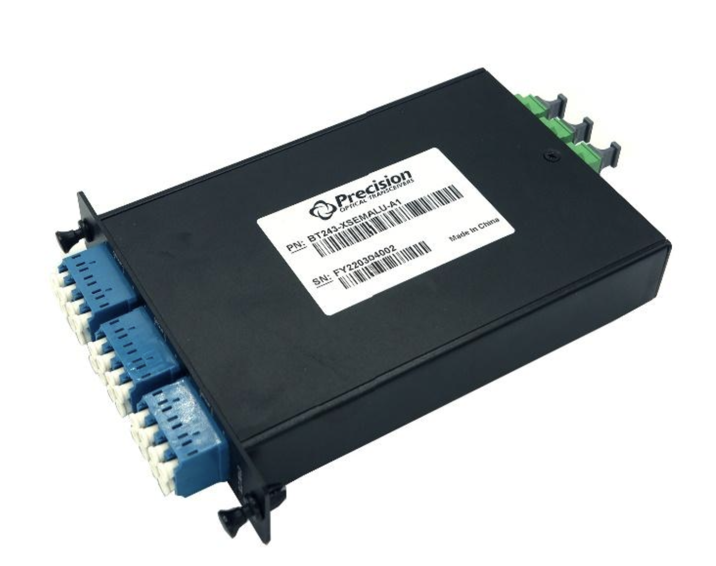
The main application of MPO connectors is to be used in breakout mode, regardless of the data rate (40G, 100G, or 400G…). For same-rack connections, a breakout fiber jumper is good enough. However, for inter-rack connections, a better solution for cable management is necessary. This is where breakout modules such as the one shown in Figure 1 are utilized. These modules are available in many configurations and often have the following features/options:
- MPO/MTP to LC/SC Connectors
- UPC or APC
- LGX Form Factor
MPO Breakout Module Types and Polarity
When using MPOs and MPO breakout modules, polarity is a great concern. With SFP and QSFP applications, it is imperative for the Tx to mate to the corresponding Rx, and vice versa. When working with a Tx & Rx pair, at some point the lines need to crossover to successfully achieve a Tx to Rx transmission. In Figure 2, the crossover occurs in the Type B MPO cable. Whatever is transmitted from the first Tx of the QSFP (blue) into the Type B MPO at its 12th position, then crosses over to position 1 at the other end of the MPO cable. From this point, it continues to the Rx port of the SFP.
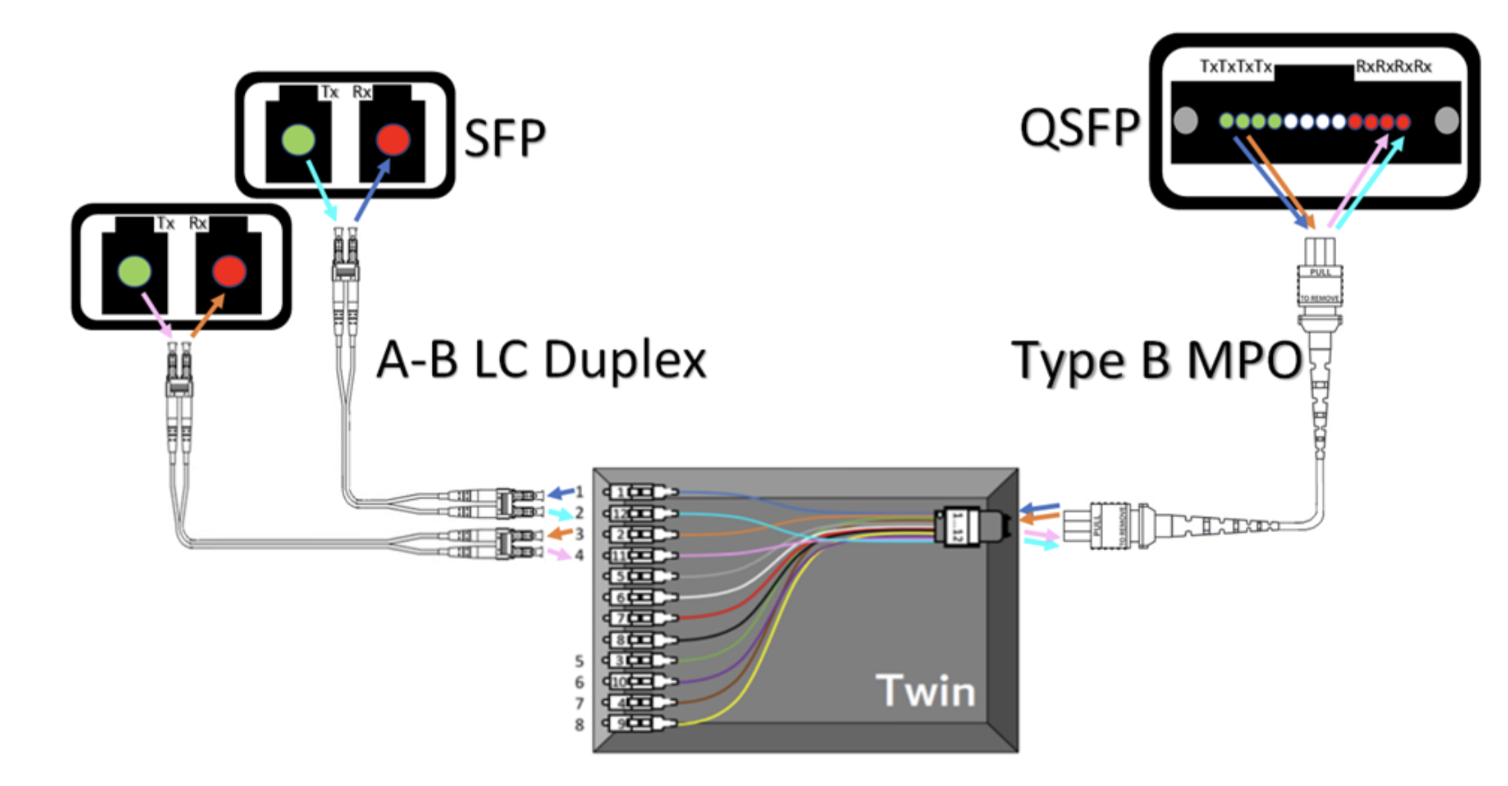
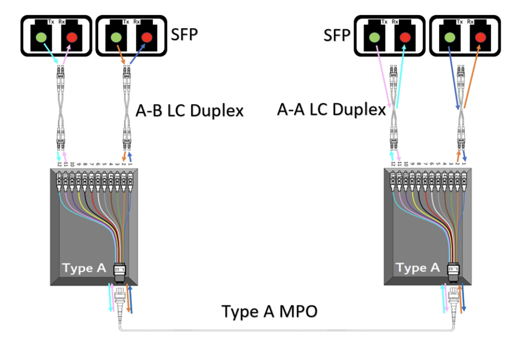
Figure 3 shows a Method A setup for SFP to SFP applications. In this setup, a Type A breakout module is used with a Type A MPO cable. The crossover occurs in the A-A LC Duplex jumpers. This means that the polarity is controlled by those specific jumpers and it requires the user to be aware of the two different LC Duplex jumpers used in the application. Other Methods can allow for the polarity to be controlled in the Breakout Modules or in the MPO cable. Knowing your setup is key to understanding how to control the polarity.
Inter Rack Connectivity
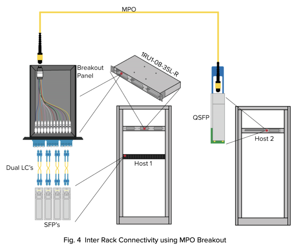
In Figure 4, we show an example of a breakout panel used to interconnect two different racks. Starting from the right, we have a QSFP transceiver that is connected in one host which is going to breakout to 4x SFPs in another host located in a different rack. Instead of using a single fiber breakout fiber jumper, a breakout panel is used, enabling a more efficient cable management and installation solution for this application. This setup is also often used in same rack breakout applications for easier cable management and troubleshooting.
Network System Design with MPO
When utilizing MPO breakout modules it’s important to also keep in mind all the things covered in our previous MPO blog such as visual alignment cues and connector features that help keep track of fiber positioning. Knowing the fiber count and polarity are essential to making a reliable connection as are fiber types (single mode vs multimode) and end faces (UPC vs APC).
At Precision OT, we’re experts in designing point-to-point layer 1 network solutions; From transceiver, to fiber jumper, to breakout module and even to in-rack management, we provide a true turn-key solution. Point-to-point, Precision OT works with the customer to meet the complete set of network requirements. Visit our website or connect with us today to find plug and play solutions for your high density network installations.