
Successful installation of a fiber-optic network employing multi-fiber push on (MPO) cables and connectors relies on several considerations, one of the most important of these is fiber polarity.
At its most basic, polarity defines the direction of current flow between two points, or poles. Negative poles have a greater number of electrons relative to positive poles; when connected, electric current will flow from negative to positive. When used in the context of fiber-optic communication, this is analogous to the flow of data in the form of light signals from transmit (Tx) to receive (Rx). A fiber-optic link can function only if Tx on one end is connected to Rx on the other, and vice versa; this is accomplished by creating a fiber polarity flip that swaps Tx for Rx at some point in the link.
Duplex Configurations and Fiber Polarity
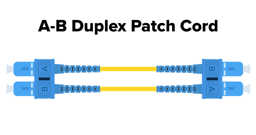
For duplex transmission, this is relatively straightforward to accomplish. An A-B duplex patch cord has a physical straight-through connection of two fibers between receiving (B) and transmitting (A) connectors. Because of this B to A and A to B connection, it is referred to as Cross-Over since the A position crosses over to the B, and vice versa. An alignment key prevents the fiber from rotating when the connectors are mated to the cable. Viewed from one end to the other, there is a single fiber connecting A to B and another single fiber connecting B to A; data flows bidirectionally and fiber polarity is maintained.
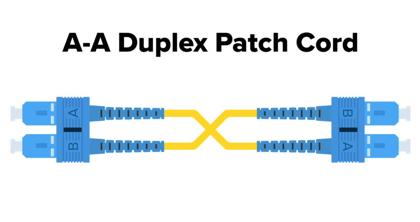
There are also A-A duplex patch cords, which are physically crossed, yet position A stays at position A and position B stays at position B so it is referred to as a Straight-Through connection. This type of cord is generally used opposite an A-B cord where the fiber polarity crossover has already occurred and needs to be maintained (rather than undone by crossing over again).
Multi-Fiber Configurations and Fiber Polarity
The industry has identified three different methods for maintaining fiber polarity in multi-fiber applications. Each involves different types of MPO cables and connectors.
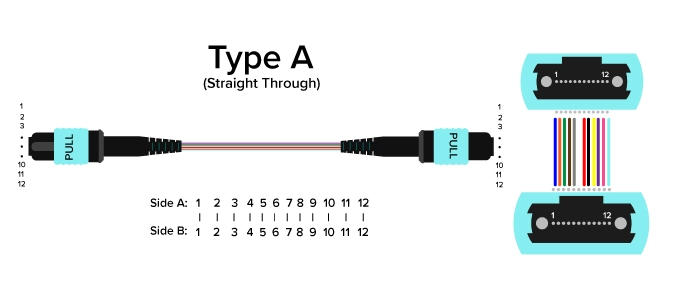
Method A uses straight-through MPO array cables to map the fibers the same way on each end of the link. They are connected by Type A adapters or cassettes, which have a “key-up/key-down” orientation. This refers to the placement of the notches that ensure alignment during connector mating on either end. When looking at the fiber end-face, fiber positions are numbered from left to right starting with P1. The P1 position is also commonly marked with a white dot on the side of the connector housing.
The Method A configuration translates to the fiber in P1 (Tx), on the left, arriving at P1 (Tx) on the right at the other end. Because Method A does not incorporate the necessary Tx to Rx fiber polarity flip, it is accomplished with an A–B duplex patch cord attached at one end and an A-A duplex cord at the other end to maintain the flip. This method is considered a simple deployment method for both single-mode and multimode channels, and it can support network extensions for ready scalability.
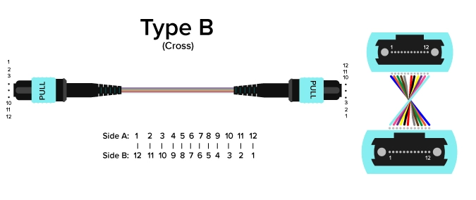
Method B uses crossed MPO array cables with Type B key-up connectors on both ends, creating the fiber polarity flip without the need for an A-A patch cord on one end; both ends can be attached to straight A-B duplex patch cords, simplifying the duplex jumpers needed. In a common 12-fiber connector, Method B translates to the fiber in P1 (Tx) arriving at P12 (Rx) on the other end, the fiber in P2 (Rx) arrives at P11 (Tx), and so on.
One drawback of this method is that the P12 fiber ultimately needs to be mated back to P1 at the end of the link. In a cassette-based system, this requires one cassette to be physically inverted and adds to the complexity of network management. Method B also does not support single-mode connections with angled physical contact (APC) polish ferrules, because the angles of the mating connectors are not complementary. One important use of a Type B array patch cord, however, is that it can be used to accomplish the fiber polarity flip in Method A polarity management of parallel signals. There, it takes the place of the A-A duplex patch cord appropriate for a duplex signal as described above.
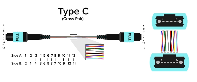
Method C shares similarities with both methods above. Like Method A, it uses Type A key-up/key-down connectors, and like Method B, both ends can be attached to straight A-B duplex patch cords. The difference is in the fiber polarity flip, which is created through crossed pairs within the MPO array cable itself: P1 (Tx) arrives at P2 (Rx) at the opposite end and vice versa, P3 and P4 are similarly crossed and so on.
This method requires more in-depth planning for fiber polarity management, and it may also be problematic for parallel signals as opposed to duplex. For instance, an eight-fiber 40G or 100G application is not supported by a 12-fiber crossed-pair array cable that would set P1-P4 as transmitting and P9 to P12 as receiving. As networking scalability at high speeds becomes increasingly important, so too does this limitation.
Conclusion
Optical fiber connectivity continues to ramp up, making fiber polarity management more important than ever. While fiber polarity in the multi-fiber era is a complex subject, the basic principles that apply to simple applications continue to serve as the building blocks for creating lasting network solutions. Contact the experts at Precision Optical Technologies to learn more.